KMDA 7473-1 FL Silence - Induction hob with integrated vapour extraction  Factual image
  • Factual image
  • Control panel image
  • Detailed image
  • Detailed image, In-situ shot
   

KMDA 7473-1 FL Silence
Induction hob with integrated vapour extraction  800 mm | Extraction and recirculation | SilenceMotor | Flex cooking area

Price: R 49 999,00 
KMDA7473-1 FL Silence

More product information

Induction hob with integrated vapour extraction  800 mm | Extraction and recirculation | SilenceMotor | Flex cooking area


  • The quietest TwoInOne from Miele – Silence motor  

    Silence motor 

    Extra-quiet: developed by Miele, this motor is 25 % quieter than its predecessor at higher air throughput levels.
  • Ample space – 4 large cooking zones incl. 2 Flex zones  

    FlexZone 

    Unique space provision: the Miele FlexZones allow you to position large pots and pans behind each other. 
  • Automatic fan power regulation – Con@ctivity

    Con@ctivity

    Innovative convenience: the cooker hood reacts automatically to settings on the hob.
  • Compact control using the numerical display – ComfortSelect Plus 

    ComfortSelect Plus 

    Compact and convenient: all cooking zones and the fan can be operated using a clear central numerical display.
  • Flexible installation – Plug & Play, ducted recirculation or vented system

Downloads - KMDA 7473-1 FL Silence

User manual & Assembly

Description Format Download
Operating instructions accessoriespdf Download
Guarantee bookletpdf Download
Product Sheetpdf Download

CAD data / BIM data

Description Format Download
3D data DWGzip Download
3D data FBXzip Download
3D data IFCzip Download
3D data RFAzip Download
3D data RVTzip Download

Installation drawings

Installation drawings

Whether you want to replace a household appliance or planning a kitchen - here you will find all the relevant installation diagrams for your Miele appliance.

If you want to download an installation diagram, please click on the appropriate image and the high-resolution version is displayed. To download, click the right mouse button and save the image on your computer.

Please note that the installation and maintenance of our equipment should only be performed by a licensed contractor. For questions, please call us and we will advise you without any obligation!

.

Installation drawing
explanations

KMDA7272-1FL, KMDA7473-1FL, KMDA7272FL, KMDA7473FL - flush

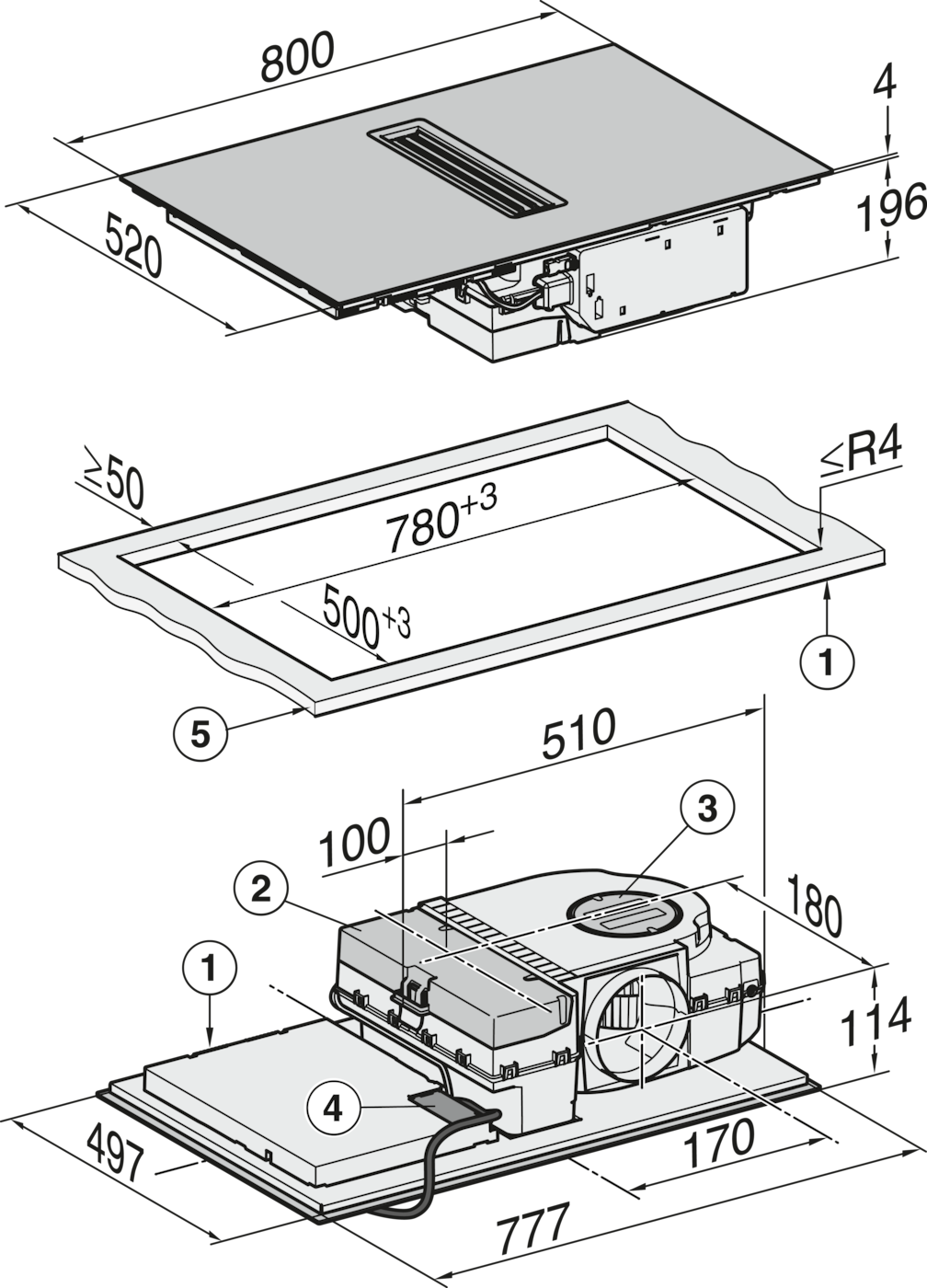
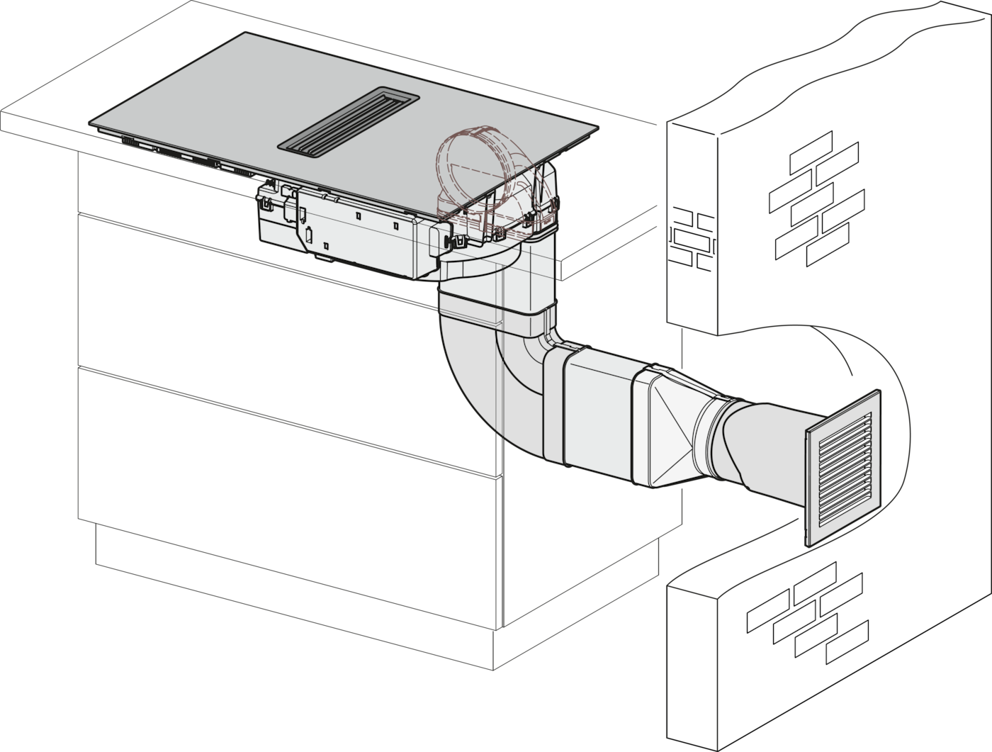
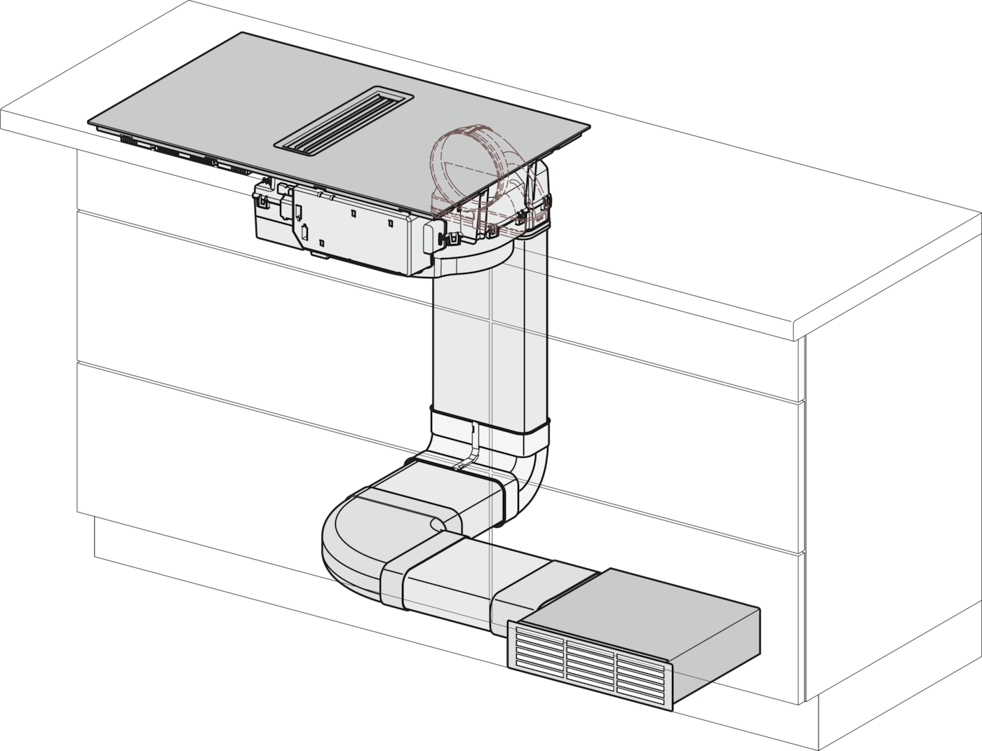
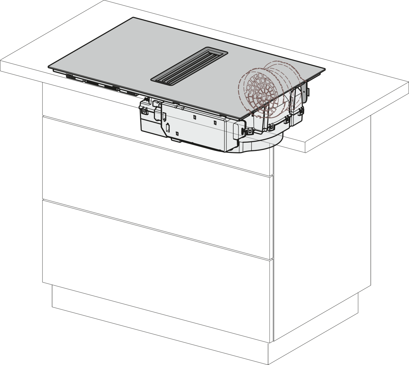
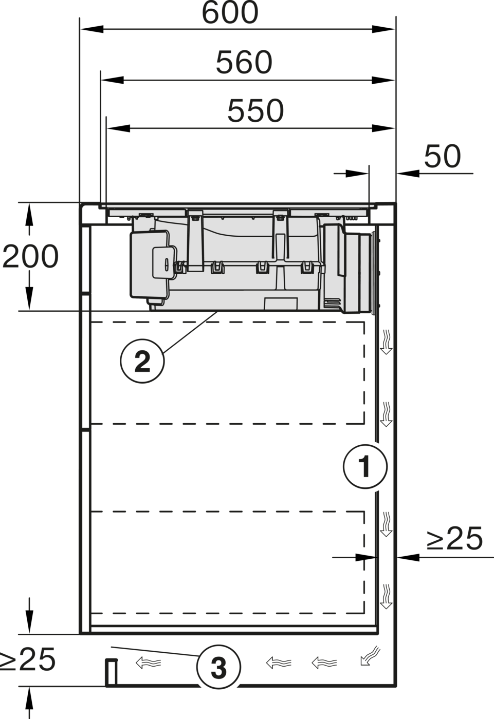
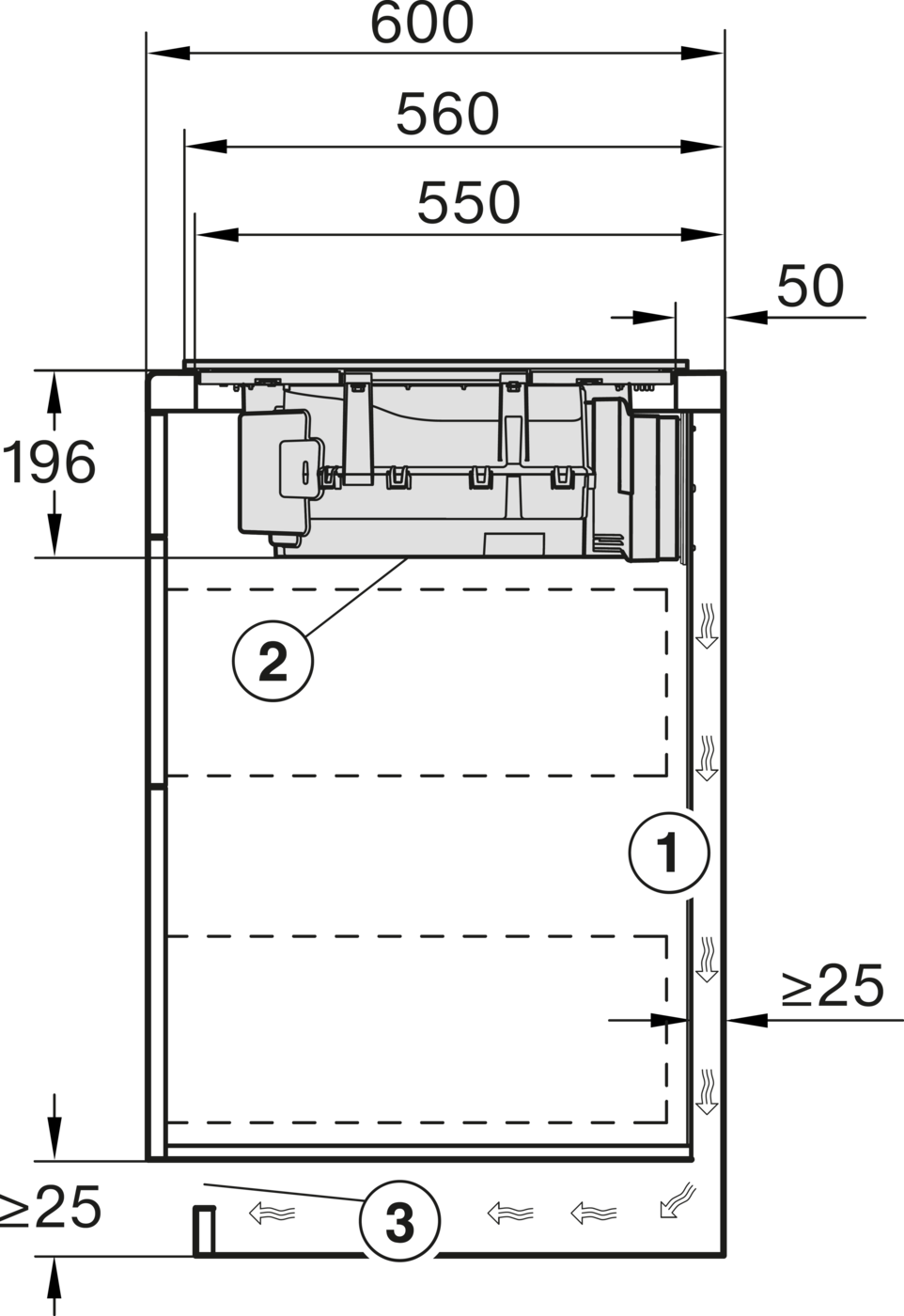
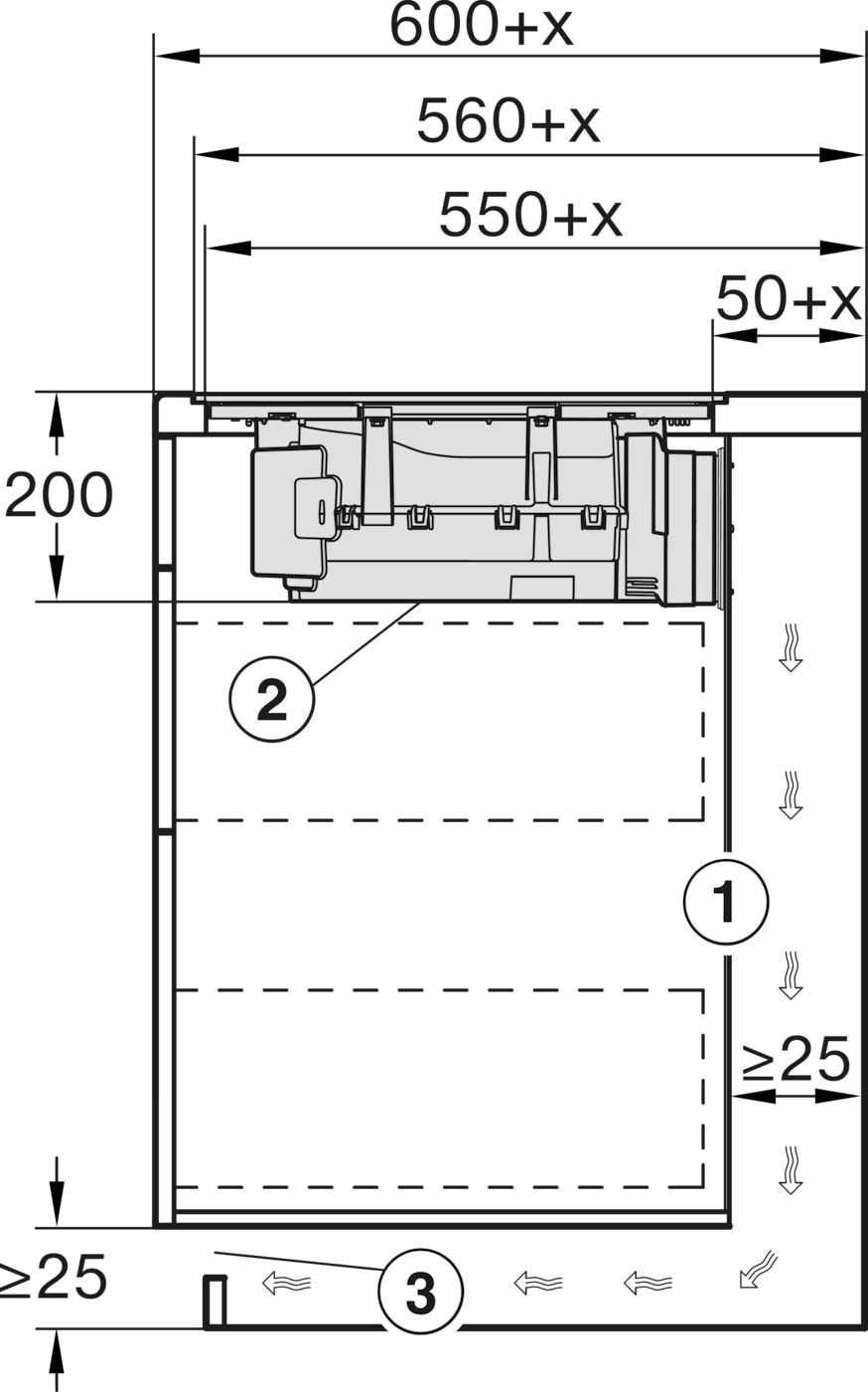
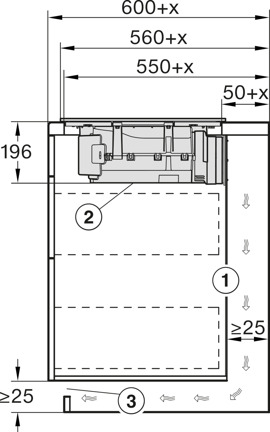
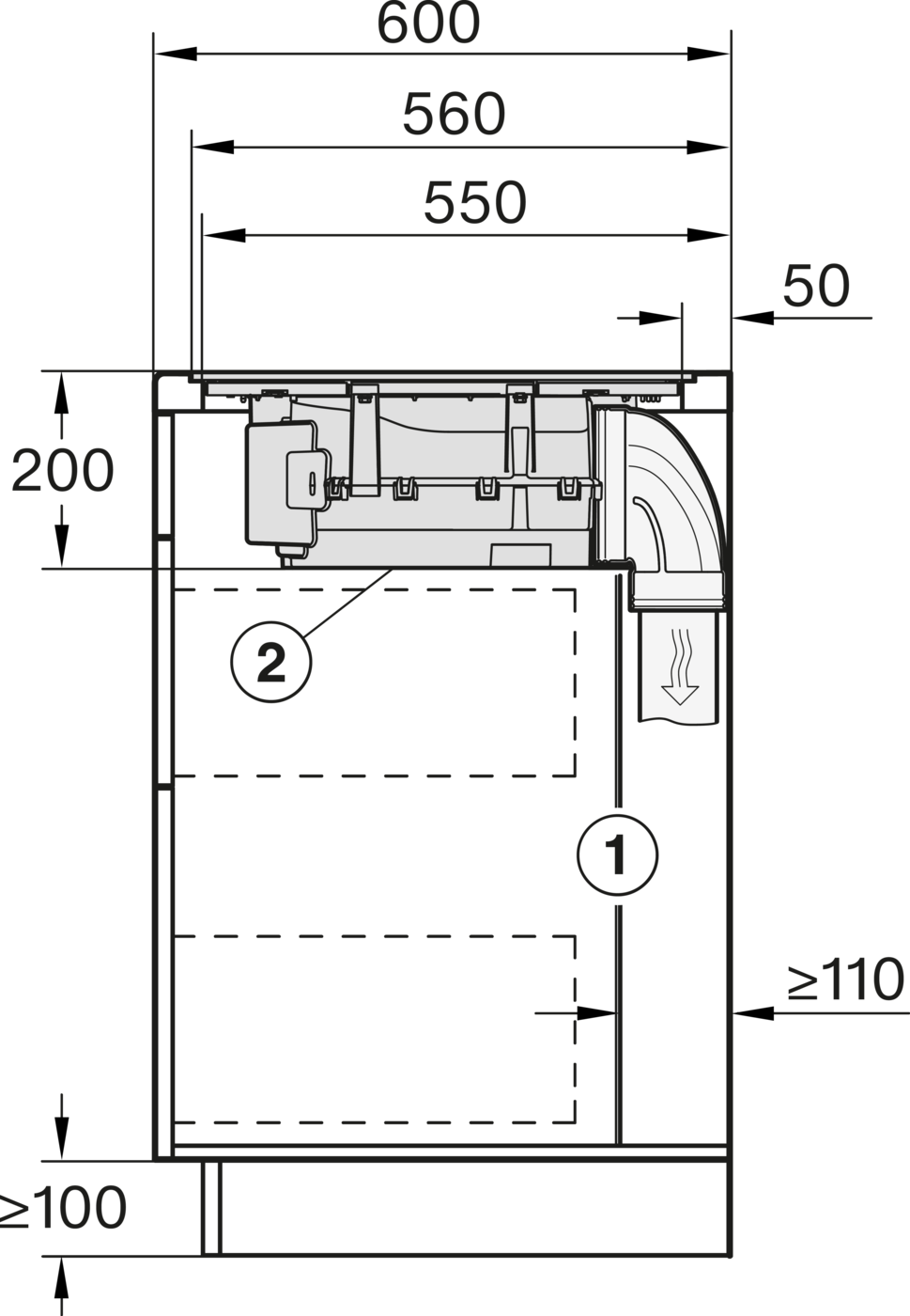
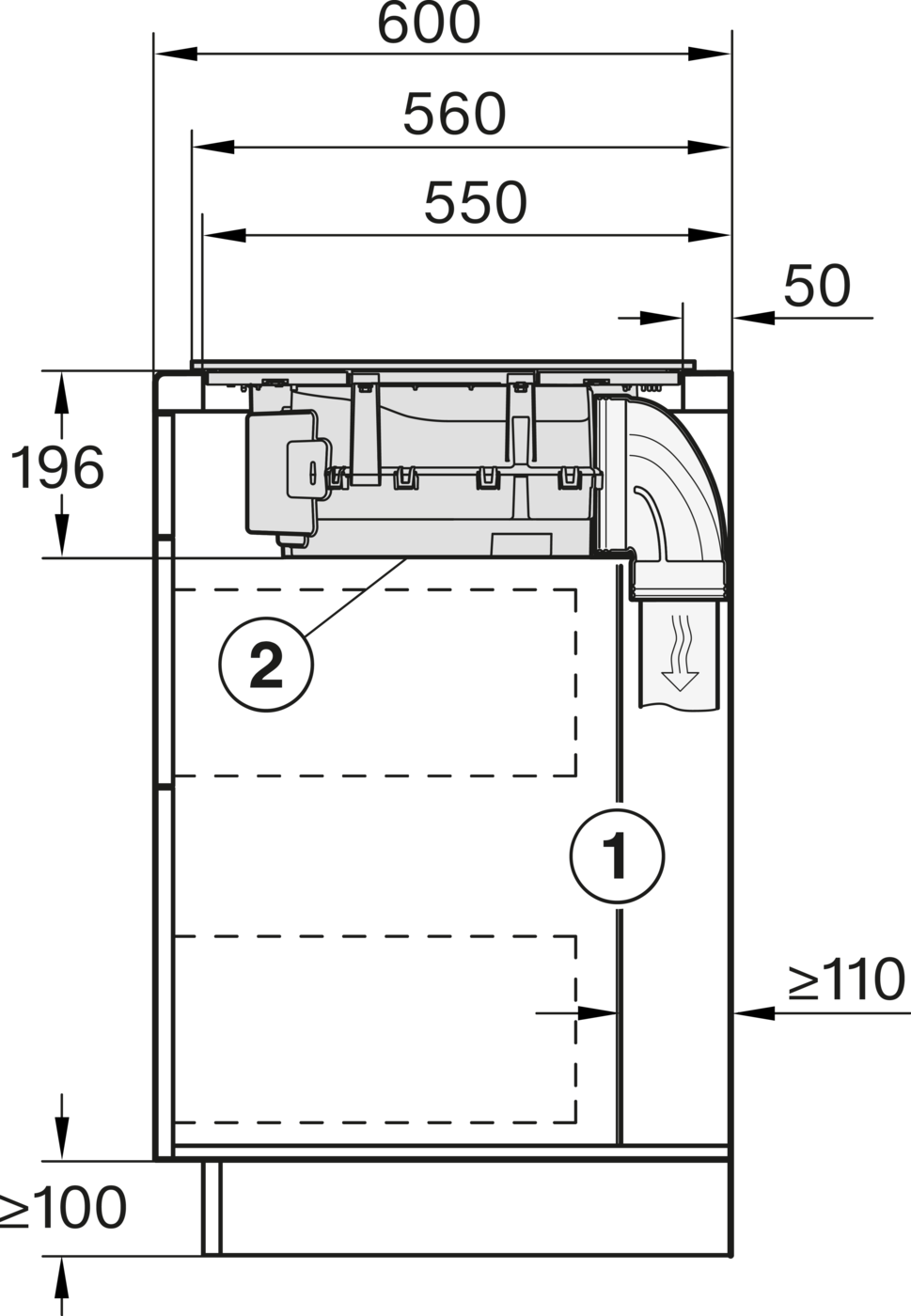
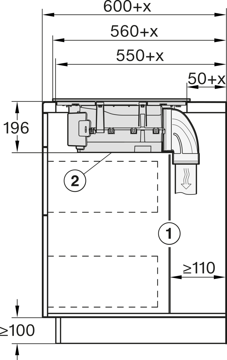
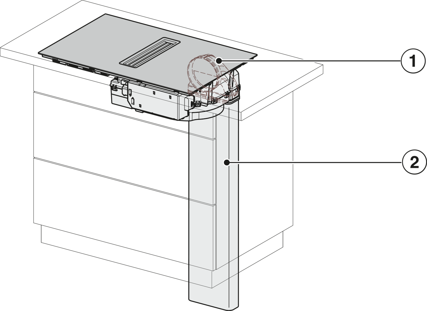
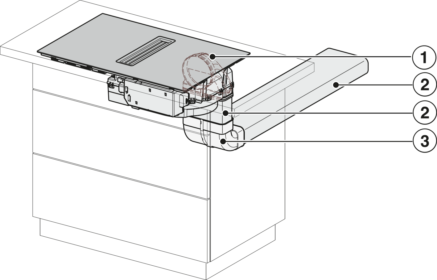
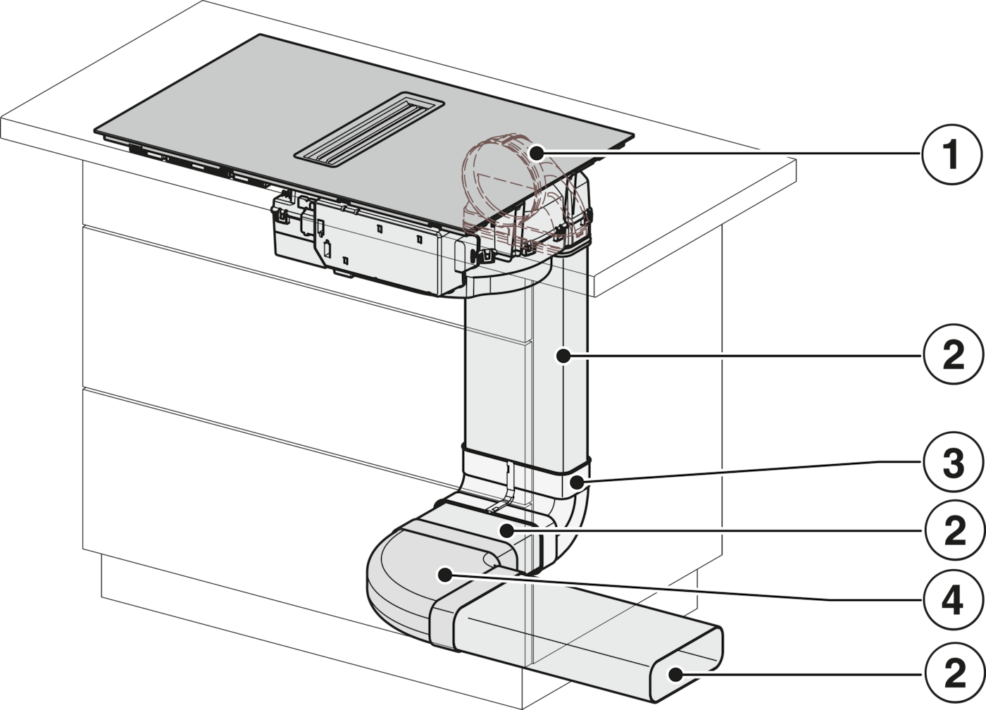
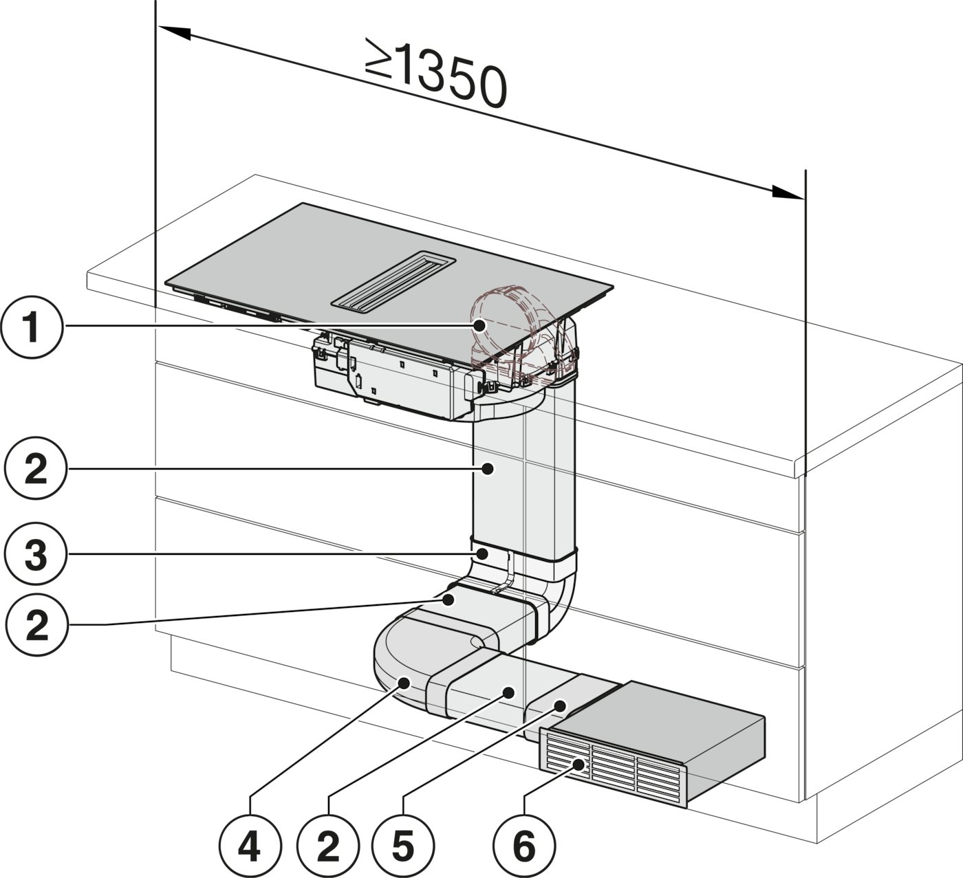
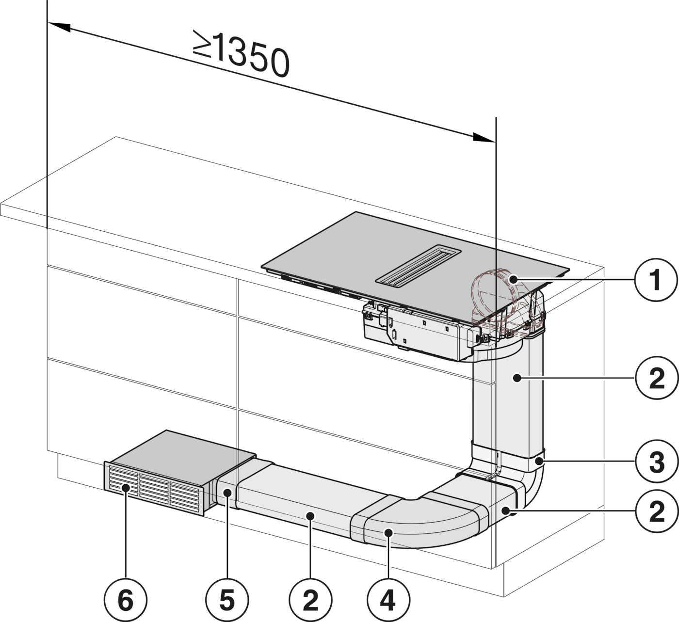
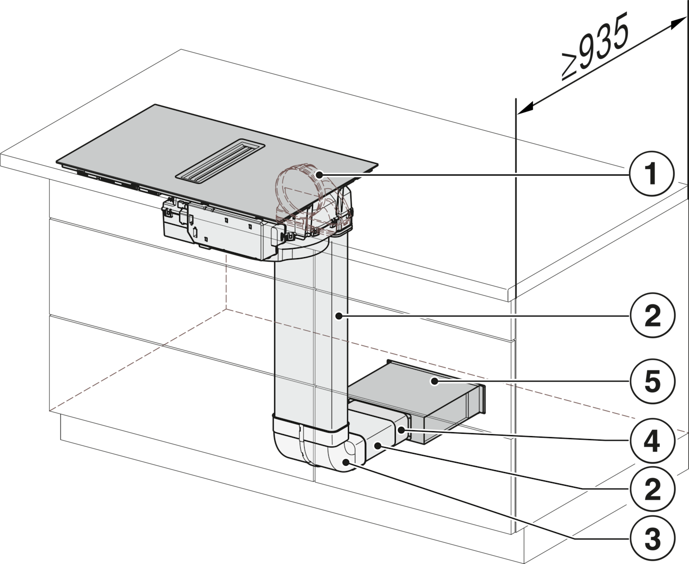
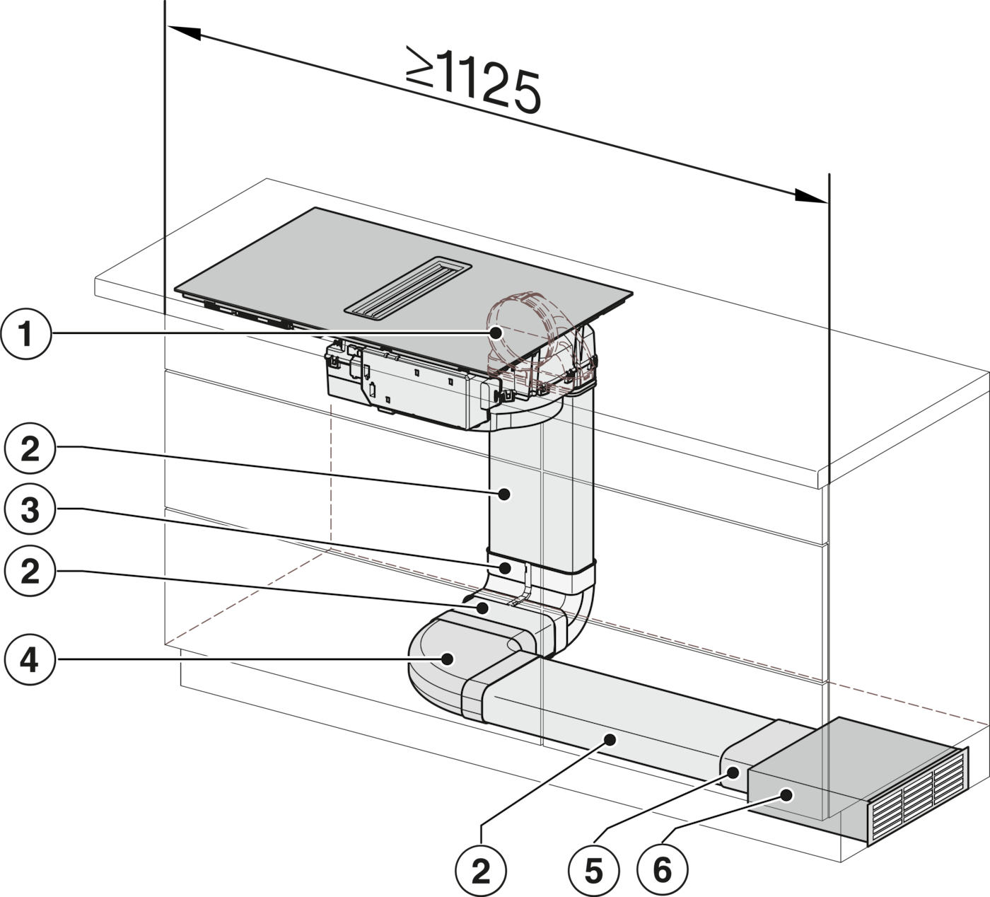
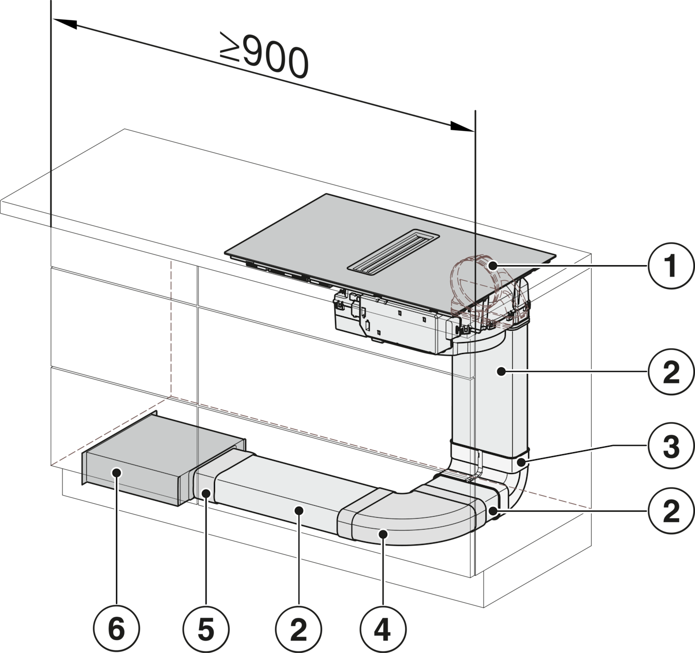
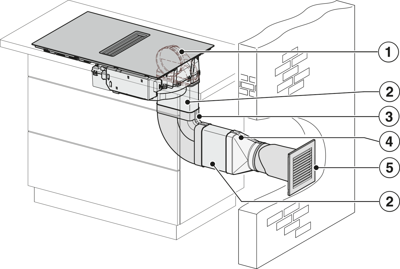
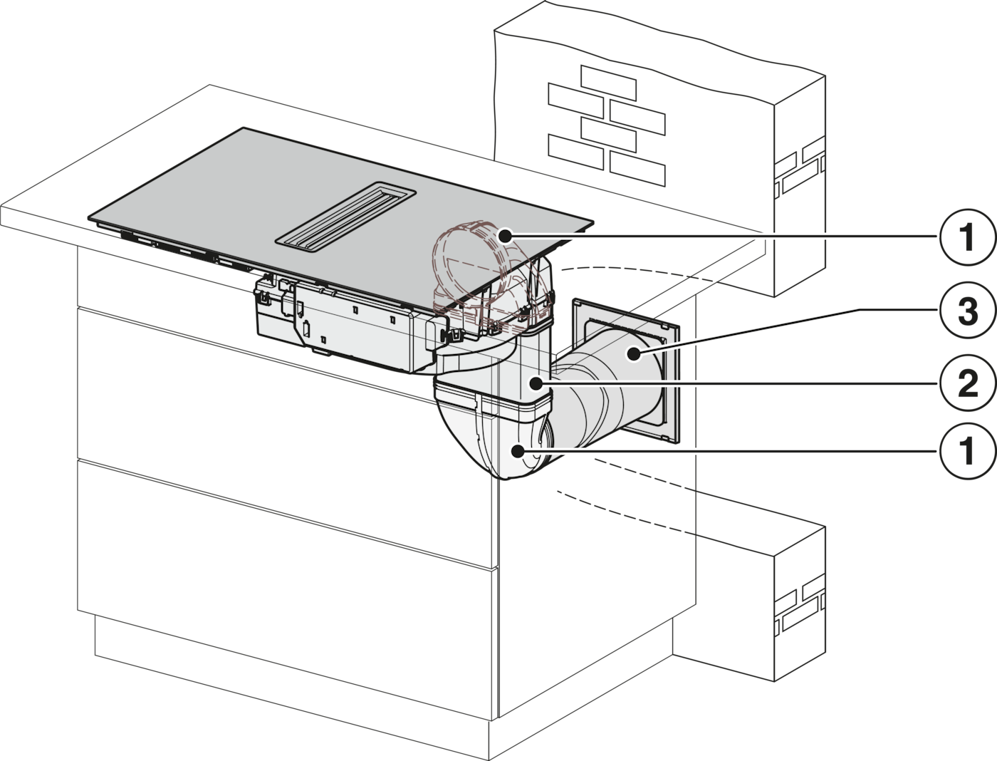
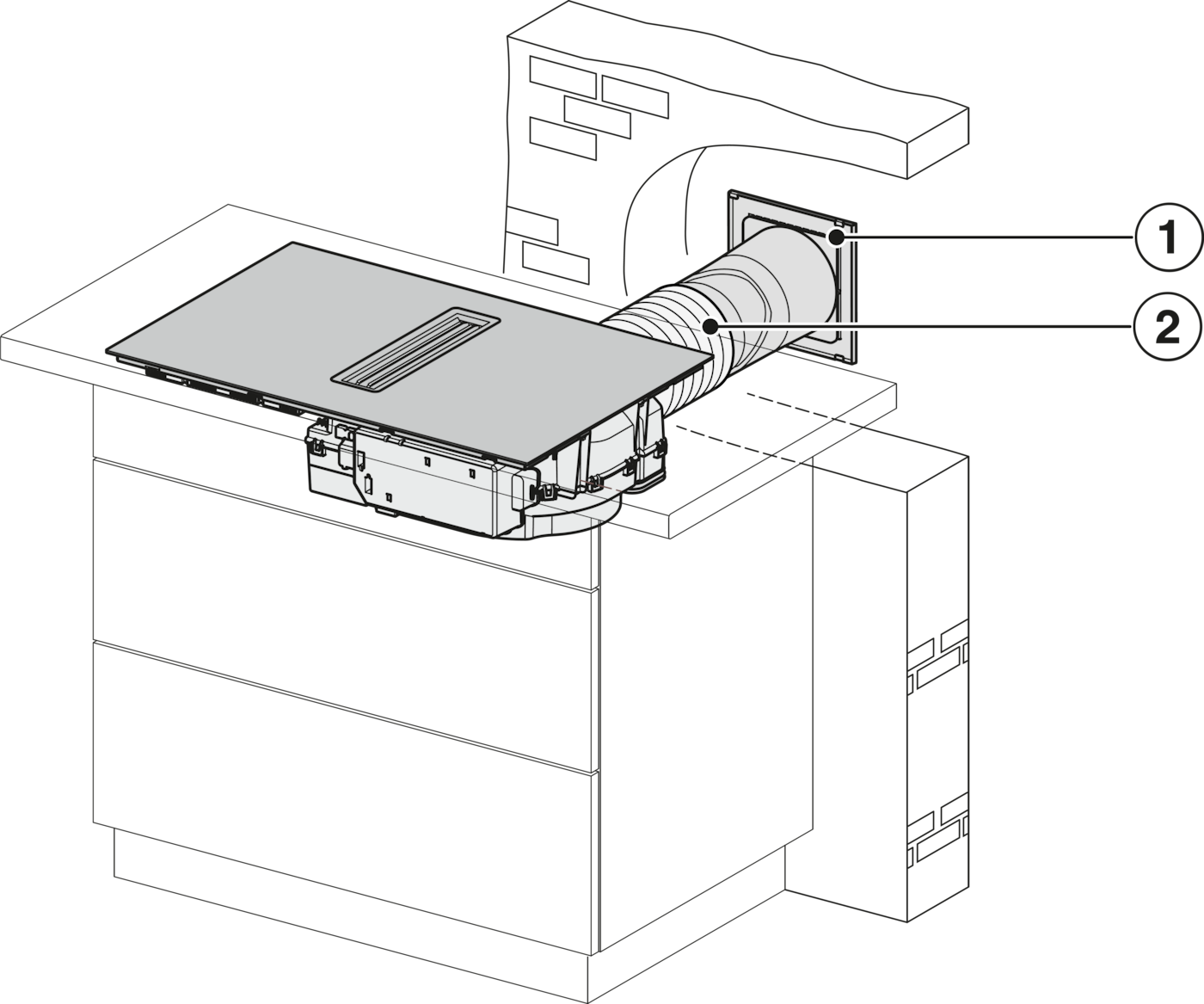
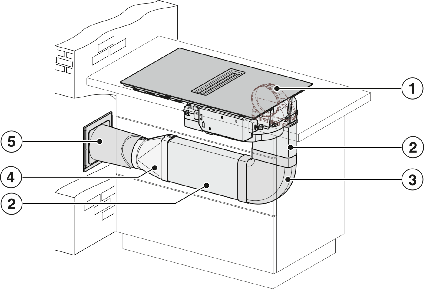
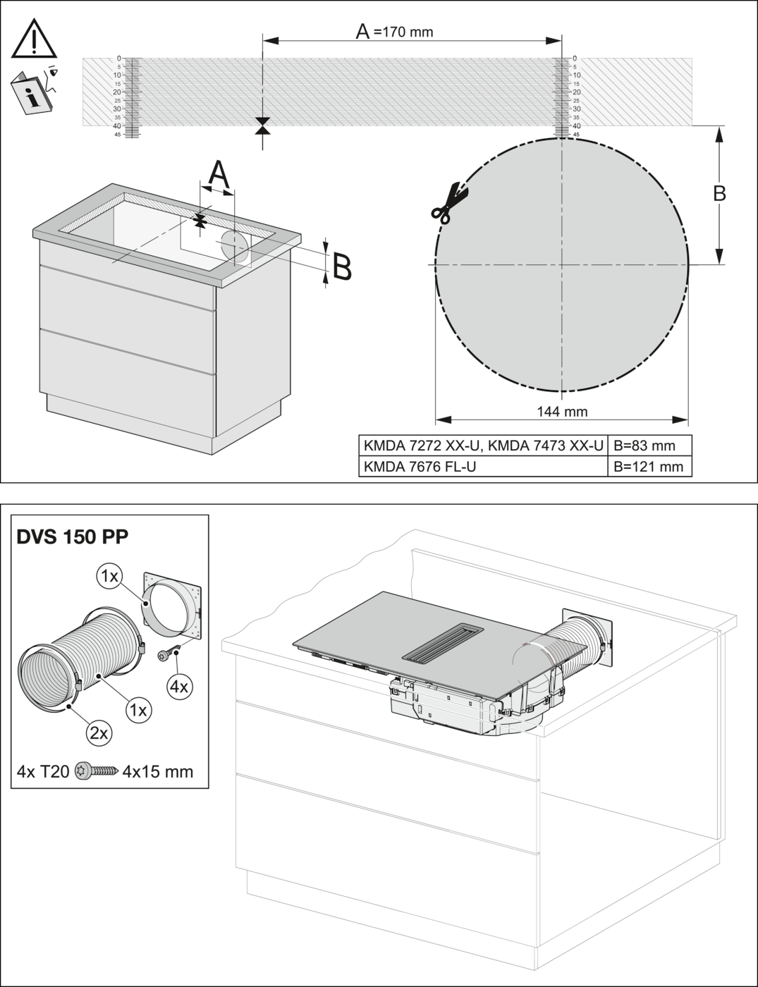
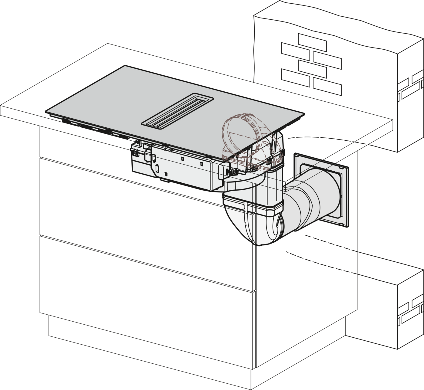
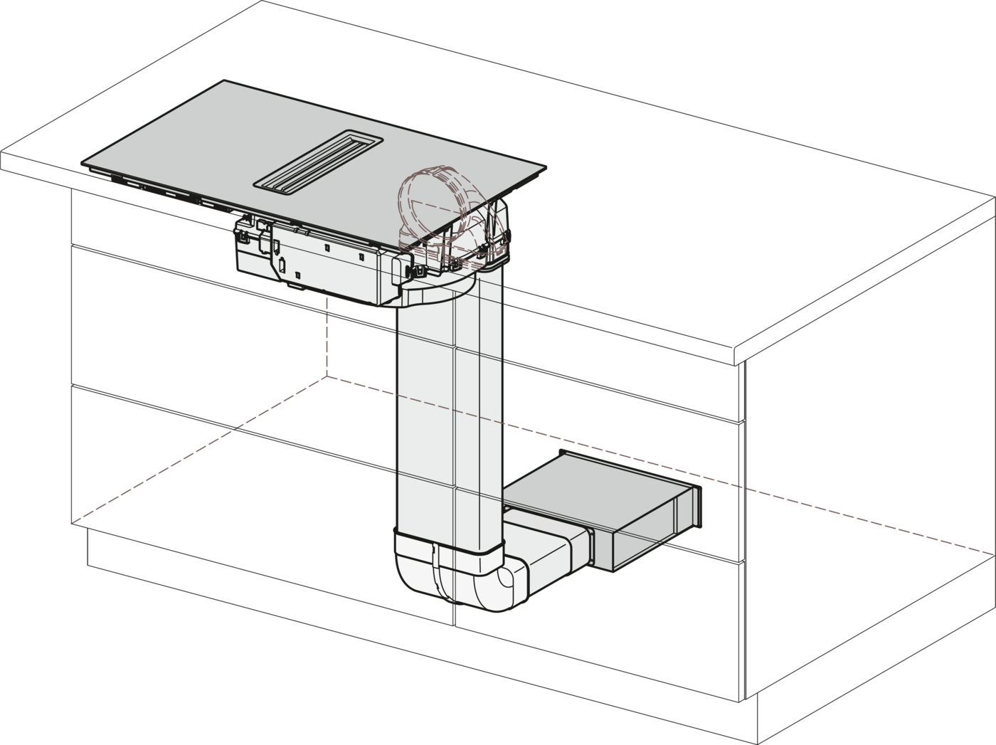
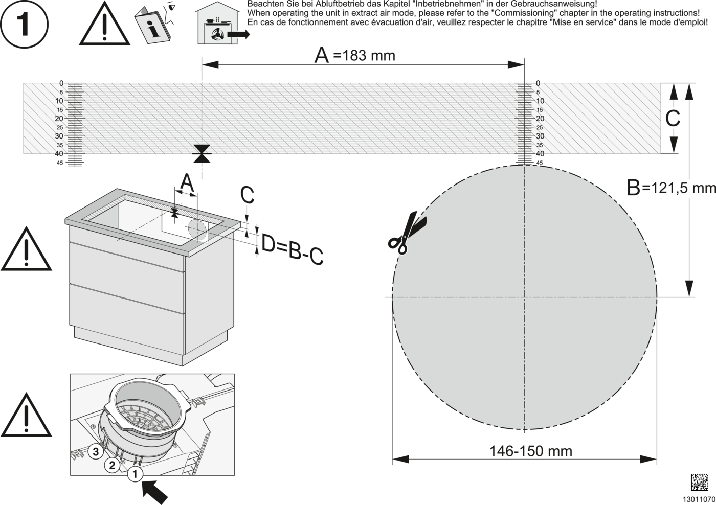
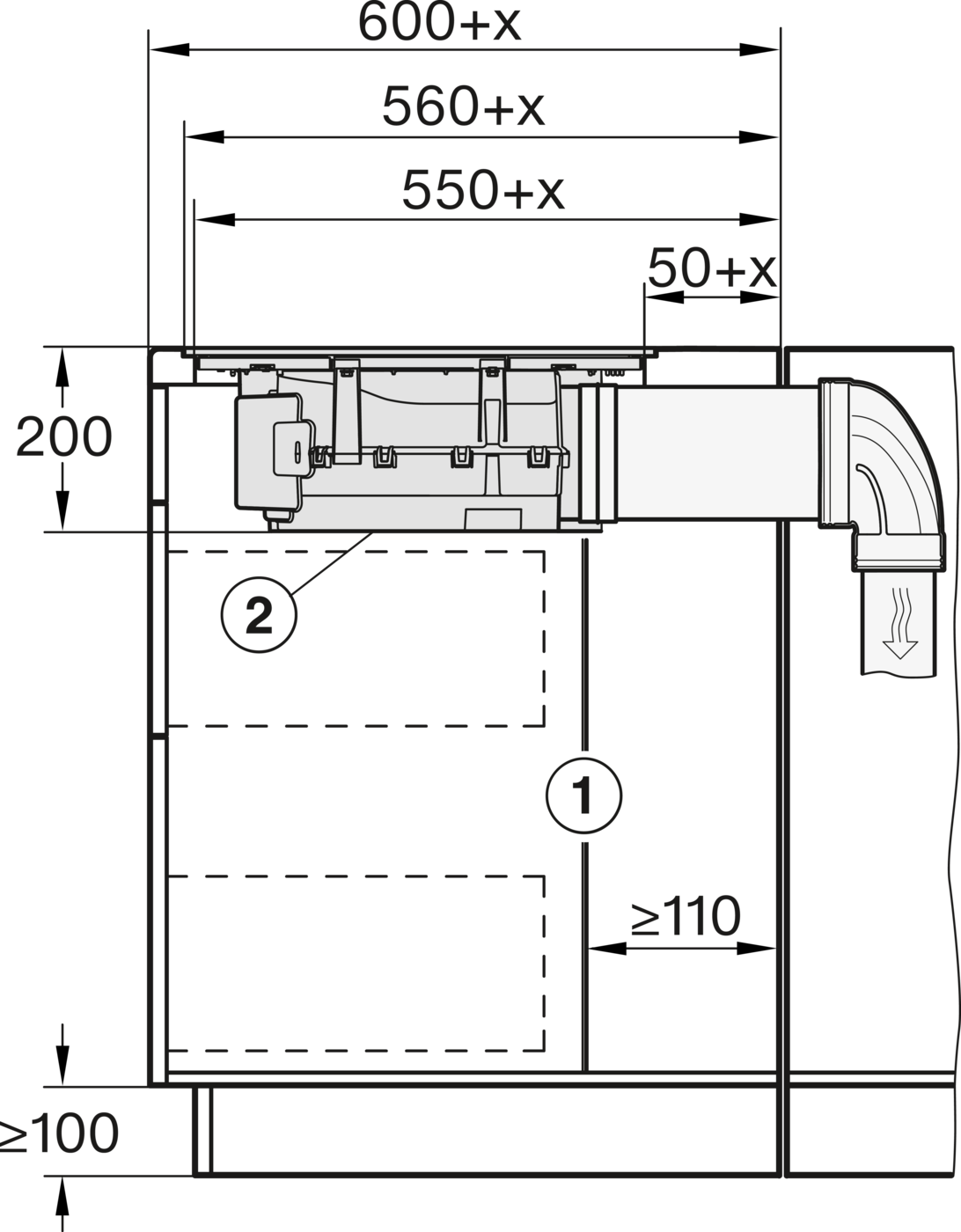
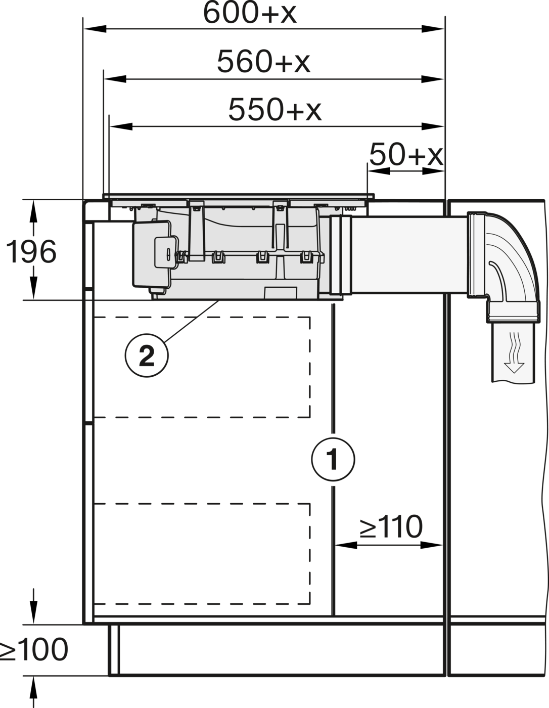
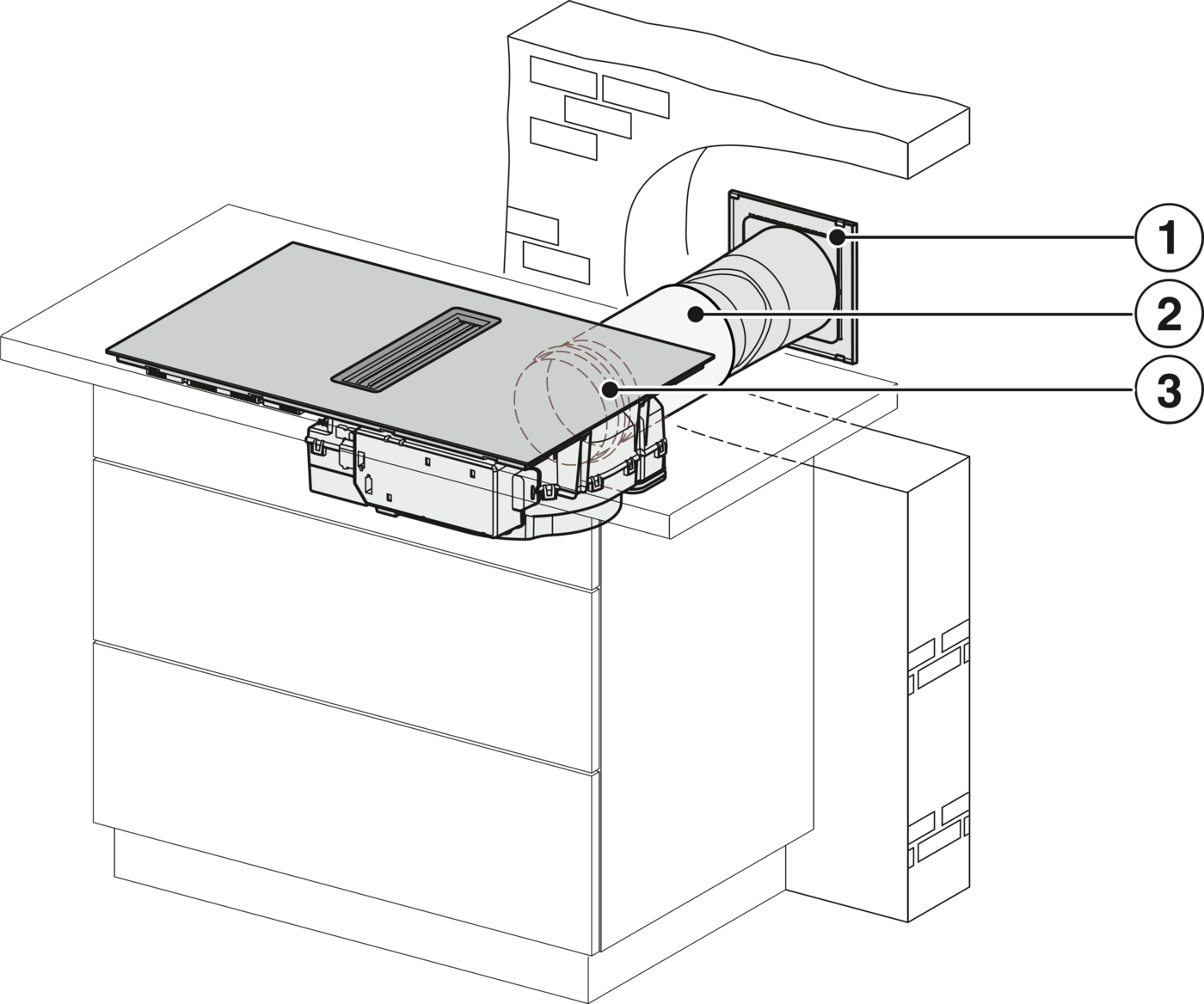
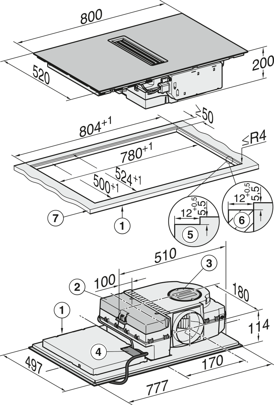
1) Front, 2) removable drip tray, 3) cleaning flap, 4) Mains connection box with mains connection cable, L = 1600 mm, 5) Step milling natural stone worktop, 6) Wooden strip 12 mm (not included in delivery), 7) Worktop thickness, Exhaust air and guided recirculation mode: ≥10 mm, Plug&play operation: ≥10 mm - ≤40 mm

Installation drawing
explanations

KMDA7272-1FL, KMDA7473-1FL, KMDA7272FL, KMDA7473FL

1) Front, 2) Removable drip tray, 3) Cleaning flap, 4) Mains connection box with mains connection cable, L = 1600 mm, 5) Worktop thickness, Exhaust air and guided recirculation mode: ≥10 mm, Plug&Play operation: ≥10 mm - ≤40 mm

Installation drawing
explanations

KMDA7272-1FL/FR, KMDA7473-1FL/FR, KMDA7272FL/FR, KMDA7473FL/FR, Exhaust air

Installation drawing
explanations

KMDA7272-1FL/FR, KMDA7473-1FL/FR, KMDA7272FL/FR, KMDA7473FL/FR, Air circulation

Installation drawing
explanations

KMDA7272-1FL/FR, KMDA7473-1FL/FR, KMDA7272FL/FR, KMDA7473FL/FR, Plug&Play

Installation drawing
explanations

KMDA7272-1FL, KMDA7473-1FL, KMDA7272FL, KMDA7473FL - Side view flush, Plug&Play

①When routing the exhaust air between the cabinet wall and an adjacent room wall or an adjacent piece of furniture, a minimum distance of 25 mm must be observed., ②The removable collection tray and the cleaning flap must be accessible after installation., ③The cross-section of the ventilation opening must be at least 425 cm²., ④Distance from the front of the lower box to the end of the plug & play adapter

Installation drawing
explanations

KMDA7272-1FL, KMDA7473-1FL, KMDA7272FL, KMDA7473FL - Side view lying on top, Plug&Play

①When routing the exhaust air between the cabinet wall and an adjacent room wall or an adjacent piece of furniture, a minimum distance of 25 mm must be observed., ②The removable collection tray and the cleaning flap must be accessible after installation., ③The cross-section of the vent opening must be at least 425 cm²., ④Distance from the front of the lower box to the end of the plug & play adapter

Installation drawing
explanations

KMDA7272-1FL, KMDA7473-1FL, KMDA7272FL, KMDA7473FL - Side view flush+X, Plug&Play

①When routing the exhaust air between the cabinet wall and an adjacent room wall or an adjacent piece of furniture, a minimum distance of 25 mm must be observed. If the carcase rear wall is 555 mm from the worktop front, the Plug&Play adapter must be extended with a supplementary set from Miele., ②The removable drip tray and the cleaning flap must be accessible after installation., ③The cross-section of the vent opening must be at least 425 cm²., ④Distance from the front of the lower box to the end of the plug & play adapter, , x Dimension by which the worktop depth is greater than 600 mm.

Installation drawing
explanations

KMDA7272-1FL, KMDA7473-1FL, KMDA7272FL, KMDA7473FL - Side view lying on top+X, Plug&Play

①When routing the exhaust air between the cabinet wall and an adjacent room wall or an adjacent piece of furniture, a minimum distance of 25 mm must be observed. If the carcase rear wall is 555 mm from the worktop front, the Plug&Play adapter must be extended with a supplementary set from Miele., ②The removable drip tray and the cleaning flap must be accessible after installation., ③The cross-section of the vent opening must be at least 425 cm²., ④Distance from the front of the lower box to the end of the plug & play adapter, , x Dimension by which the worktop depth is greater than 600 mm.

Installation drawing
explanations

KMDA7272-1FL, KMDA7473-1FL, KMDA7272FL, KMDA7473FL - Side view flush+X

①The rear wall of the cabinet must be removable for servicing. A minimum distance of 110 mm must be maintained for routing the exhaust air duct between the cabinet wall and an adjacent room wall or furniture., ②The removable collection tray and the cleaning flap must be accessible after installation., , x Dimension by which the worktop depth is greater than 600 mm.

Installation drawing
explanations

KMDA7272-1FL, KMDA7473-1FL, KMDA7272FL, KMDA7473FL - Side view flush

①The rear wall of the cabinet must be removable for servicing. A minimum distance of 110 mm must be maintained for routing the exhaust air duct between the cabinet wall and an adjacent room wall or furniture., ②The removable collection tray and the cleaning flap must be accessible after installation.

Installation drawing
explanations

KMDA7272-1FL, KMDA7473-1FL, KMDA7272FL, KMDA7473FL - Side view lying on top

①The rear wall of the cabinet must be removable for servicing. A minimum distance of 110 mm must be maintained for routing the exhaust air duct between the cabinet wall and an adjacent room wall or furniture., ②The removable collection tray and the cleaning flap must be accessible after installation.

Installation drawing
explanations

KMDA7272-1FL, KMDA7473-1FL,KMDA7272FL, KMDA7473FL - Side view lying on top+X

①The rear wall of the cabinet must be removable for servicing. A minimum distance of 110 mm must be maintained for routing the exhaust air duct between the cabinet wall and an adjacent room wall or furniture., ② The removable collection tray and the cleaning flap must be accessible after installation., , x Dimension by which the worktop depth is greater than 600 mm.

Installation drawing
explanations

KMDA7272-1FL/FR, KMDA7473-1FL/FR, KMDA7272FL/FR, KMDA7473FL/FR - Installation variant 1 Basis

1) DFK-AK 90, 2) DFK-R 1000

Installation drawing
explanations

KMDA7272-1FL/FR, KMDA7473-1FL/FR, KMDA7272FL/FR, KMDA7473FL/FR - Installation variant 2 Basis

1) DFK-AK 90, 2) DFK-R 1000, 3) DFK-BV 90

Installation drawing
explanations

KMDA7272-1FL/FR, KMDA7473-1FL/FR, KMDA7272FL/FR, KMDA7473FL/FR -Installation variant 3 Basis

1) DFK-AK 90, 2) DFK-R 1000, 3) DFK-BV 90, 4) DFK-BH 90

Installation drawing
explanations

KMDA7272-1FL/FR, KMDA7473-1FL/FR, KMDA7272FL/FR, KMDA7473FL/FR - Installation variant 4 Circulating air

1) DFK-AK 90, 2) DFK-R 1000, 3) DFK-BV 90, 4) DFK-BH 90, 5) DFK-V, 6) DUU 1500, , The minimum width of the cabinet is 1350 mm.

Installation drawing
explanations

KMDA7272-1FL/FR, KMDA7473-1FL/FR, KMDA7272FL/FR, KMDA7473FL/FR - Installation variant 5 Circulating air

1) DFK-AK 90, 2) DFK-R 1000, 3) DFK-BV 90, 4) DFK-BH 90, 5) DFK-V, 6) DUU 1500, , The minimum width of the cabinet is 1350 mm.

Installation drawing
explanations

KMDA7272-1FL/FR, KMDA7473-1FL/FR, KMDA7272FL/FR, KMDA7473FL/FR - Installation variant 6 Circulating air

1) DFK-AK 90, 2) DFK-R 1000, 3) DFK-BV 90, 4) DFK-V, 5) DUU 1500, , The minimum depth of the cabinet is 935 mm.

Installation drawing
explanations

KMDA7272-1FL/FR, KMDA7473-1FL/FR, KMDA7272FL/FR, KMDA7473FL/FR - Installation variant 13 Circulating air

1) DFK-AK 90, 2) DFK-R 1000, 3) DFK-BV 90, 4) DFK-BH 90, 5) DFK-V, 6) DUU 1500, , The minimum width of the cabinet is 1125 mm.

Installation drawing
explanations

KMDA7272-1FL/FR, KMDA7473-1FL/FR, KMDA7272FL/FR, KMDA7473FL/FR - Installation variant 14 Circulating air

1) DFK-AK 90, 2) DFK-R 1000, 3) DFK-BV 90, 4) DFK-BH 90, 5) DFK-V, 6) DUU 1500, , The minimum width of the cabinet is 900 mm.

Installation drawing
explanations

KMDA7272-1FL/FR, KMDA7473-1FL/FR, KMDA7272FL/FR, KMDA7473FL/FR - Installation variant 9 Exhaust air

1) DFK-AK 90, 2) DFK-R 1000, 3) DFK-BH 90, 4) DFK-A, 5) DMK 150-1

Installation drawing
explanations

KMDA7272-1FL/FR, KMDA7473-1FL/FR, KMDA7272FL/FR, KMDA7473FL/FR - Installation variant 10 Exhaust air

1) DFK-AK 90, 2) DFK-R 1000, 3) DMK 150-1

Installation drawing
explanations

KMDA7272-1FL/FR, KMDA7473-1FL/FR, KMDA7272FL/FR, KMDA7473FL/FR - Installation variant 11 Exhaust air

1) DMK 150-1, 2) Flex hose

Installation drawing
explanations

KMDA7272-1FL/FR, KMDA7473-1FL/FR, KMDA7272FL/FR, KMDA7473FL/FR - Installation variant 12 Exhaust air

1) DFK-AK 90, 2) DFK-R 1000, 3) DFK-BH 90, 4) DFK-A, 5) DMK 150-1

Installation drawing
explanations

Installation plan DVS150PP

Installation drawing
explanations

KMDA7272-1FL/FR, KMDA7473-1FL/FR, KMDA7272FL/FR, KMDA7473FL/FR, Exhaust air

Installation drawing
explanations

KMDA7272-1FL/FR, KMDA7473-1FL/FR, KMDA7272FL/FR, KMDA7473FL/FR, Air circulation

Installation drawing
explanations

KMDA7272-1FL/FR, KMDA7473-1FL/FR - surface installation, 21 cm, drilling template

Installation drawing
explanations

KMDA7272-1FL, KMDA7473-1FL - flush installation, drilling template, Installation depth 21 cm

Installation drawing
explanations

KMDA7272-1FL, KMDA7473-1FL - flush installation, drilling template, Installation depth 20 cm

Installation drawing
explanations

KMDA7272-1FL/FR, KMDA7473-1FL/FR - surface installation, drilling template

Image(s) as examples, to illustrate